
When you're settled into a window seat, the safety card often becomes a small aviation lesson. You may find yourself tracing the cutaway airplane with a finger, wondering which shape is the wing box, where the engines attach, or why the tail has so many separate surfaces. For readers of Haute Jets Journal, this guide turns that tiny picture into a practical, plain-English reference.
A parts of a plane diagram makes more sense when you read it in layers. Start with the five structural groups, identify the components inside each group, then learn the ATA chapter language mechanics use to locate systems, subassemblies, and parts. The vocabulary suits curious passengers, student pilots, and aviation hobbyists alike. You won't need an engineering background, and each term is explained so you can recognize and repeat it on the ground.
A Quick Tour Before Takeoff
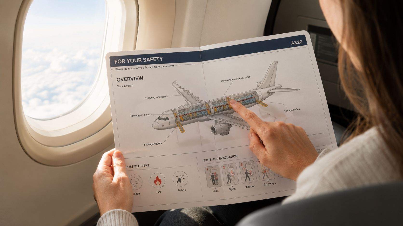
Begin at the nose and move toward the tail. A typical diagram labels the radome, cockpit, fuselage, wings, engines, landing gear, stabilizers, rudder, elevators, flaps, spoilers, and ailerons. Those labels aren't scattered decoration. Each one points to a structure or surface with a job in flight.
The easiest way to remember the airplane is to ask three questions:
- What carries the load? The fuselage carries people and cargo, while the wings support most of the aircraft's lift-producing work.
- What moves the airplane? The powerplant produces thrust, which pushes the aircraft forward.
- What directs the airplane? The empennage and movable control surfaces manage pitch, yaw, roll, stability, and maneuvering.
The five major groups provide the outer frame. Inside them, you'll find structural items such as spars, ribs, skins, bulkheads, fairings, struts, and attachment points. A technical diagram may then add system lines, wiring, actuators, sensors, and part numbers.
Reading habit: Start with the large shape, then follow each label inward to the component and its function.
The sections ahead follow that same path. First comes the airframe's five structural groups. Then we move through the fuselage, wings, tail, engines, avionics, and landing gear before decoding the ATA chapter system. The final tables condense the vocabulary into a reference you can save for a flight, an airshow, or a maintenance-hangar visit.
The Five Core Structural Groups
The FAA's basic structural framework uses fuselage, wings, empennage, landing gear, and powerplant as the five core groups. The FAA Pilot's Handbook explanation of airplane structure describes the fuselage as the central body that carries crew, passengers, and cargo while connecting the wings and tail assembly.
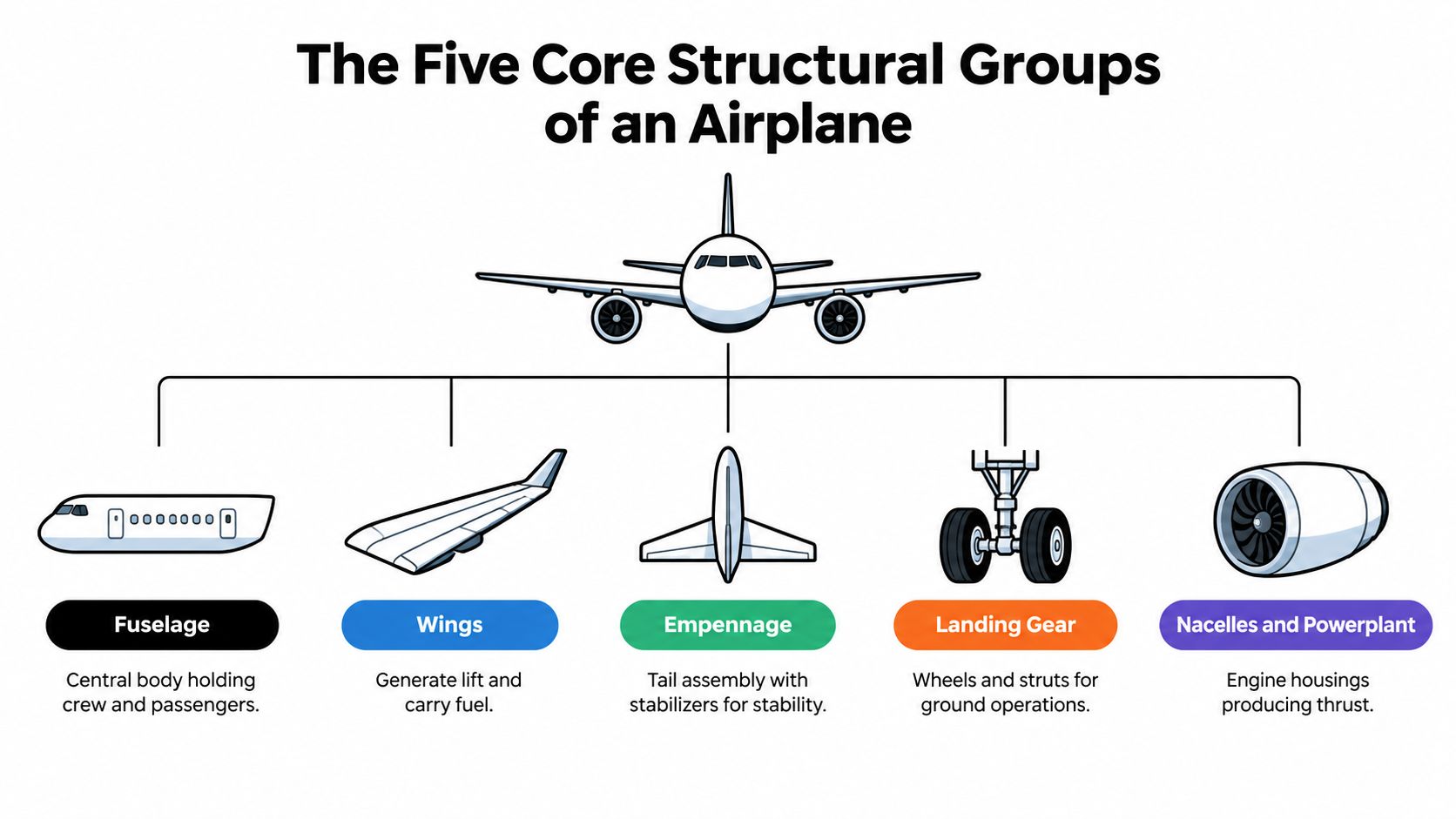
Think of the five groups as the airplane's outside map:
- Fuselage: This central body houses the flight deck, cabin, cargo areas, systems, and structural connections. It gives the aircraft its main length and provides the pressure shell on a pressurized airliner.
- Wings: These broad surfaces generate most of the lift and may contain fuel tanks, flight-control surfaces, high-lift devices, and engine attachment structures.
- Empennage: This is the complete tail assembly, including the vertical and horizontal stabilizers plus their movable control surfaces. It helps keep the aircraft stable and controls pitch and yaw.
- Landing gear: Wheels, tires, struts, brakes, doors, and related supports hold the aircraft on the ground and absorb loads during taxi, takeoff, and landing.
- Powerplant: The engine and its supporting installation create thrust. On a jet, the nacelle and pylon connect the engine to the wing or fuselage while enclosing and supporting associated equipment.
Avionics and cabin furnishings usually appear as overlays rather than a separate sixth structural group. The flight deck, radios, displays, galleys, seats, and lavatories are important, but they fit inside or onto the main airframe framework.
The connections matter. The fuselage joins the wing roots, the tail attaches at the aft body, the landing gear transfers ground loads into the structure, and the powerplant feeds thrust into the aircraft through its mounts. Readers who want a broader perspective on how engineers evaluate load paths can also consult this overview of structural analysis for mobile machinery from MA Hydraulics Ltd. The next labels become easier once this five-part map is familiar.
Fuselage and Crew Compartment Parts
A fuselage diagram is easiest to read from front to back. At the nose, the radome is the aerodynamic nose covering that protects the weather radar antenna while allowing the radar signal to pass through. Behind it, the flight deck windscreens and cockpit windows give pilots forward and side visibility.
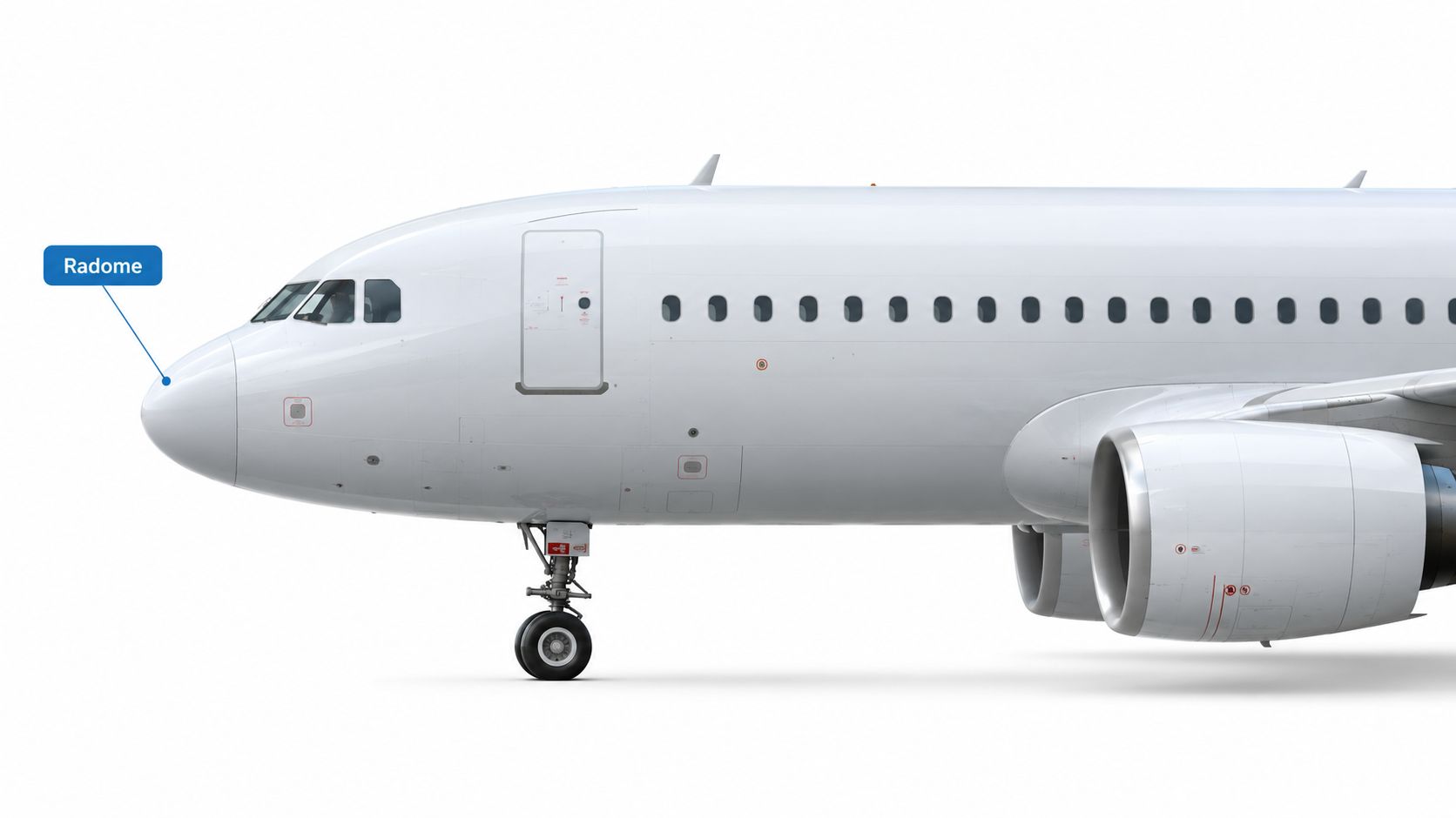
The nose landing gear well is the recessed bay that receives the nose gear when it retracts. Passenger-facing drawings may show the forward passenger door near this area, while the aft passenger doors appear farther along the cabin. Cabin windows are openings in the fuselage side that provide light and visibility, with their surrounding structure integrated into the pressure shell.
The shell that holds pressure
A pressure bulkhead is a strong partition that closes off a pressurized section of the fuselage. The aft pressure bulkhead, near the tail, forms the rear boundary of the main pressurized cabin on many airliners. These parts aren't just walls. They help contain the pressure difference between the cabin and the outside atmosphere.
The wing-to-fuselage fairing, often called the center section fairing, covers and smooths the area where the wing roots meet the body. Its aerodynamic purpose is to reduce abrupt airflow changes around that junction. A diagram may show the fairing as a broad curved panel rather than as a structural part of the wing or fuselage itself.
Inside the pressure shell, crew-rest compartments, galleys, lavatories, seats, and stowage areas occupy carefully arranged zones. A passenger safety card rarely labels them all because its purpose is emergency orientation, not maintenance identification. A detailed cabin or interior reference can show the arrangement more clearly, including the relationship between the cabin layout and the aircraft's structural shell. Haute Jets' private jet interior guide offers useful context for understanding how passenger spaces fit into an aircraft.
When you see a fuselage label, ask whether it identifies the body, a door or window, a pressure boundary, or an aerodynamic fairing. That simple distinction keeps the nose-to-tail tour organized. The wings add the next major layer, because they combine structural strength with the surfaces that actively shape the airflow.
Wings and Their Control Surfaces
The wing is the aircraft's primary lift-generating surface. A wing diagram usually begins with the wing root, where the wing joins the fuselage, and the wingtip, its outer end. The leading edge faces forward into the airflow, while the trailing edge faces aft.
Inside the wing, spars run spanwise and carry major bending loads. Ribs give the wing its aerodynamic shape and transfer loads between the skin and spars. Stringers reinforce the skin along the length of the structure. Together, these components form a strong, shaped surface rather than a hollow decorative panel.

Follow the airflow from front to back
At the leading edge, slats are movable high-lift devices. They extend to help the wing produce lift at slower speeds, including during takeoff and approach. Along the trailing edge, flaps change the wing's effective shape, increasing lift while also creating drag for takeoff and landing.
On the upper surface, spoilers, also called speedbrakes in some operating contexts, rise into the airflow. They reduce lift and add drag, helping the aircraft slow down or descend. The ailerons sit toward the outboard trailing edge and move in opposite directions. One rises while the other lowers, creating a rolling motion around the aircraft's longitudinal axis.
Winglets rise or angle outward at the wingtips. They help manage the airflow around the tip and can reduce induced drag. Fairings smooth transitions around joints, flap tracks, landing gear attachments, and other areas where exposed edges would disturb the airflow.
A short visual explanation can make the difference between memorizing labels and understanding them:
The NASA guide to airplane parts and functions connects the wing to lift and identifies the ailerons, elevator, and rudder with roll, pitch, and yaw control. In ATA documentation, flight controls use Chapter 27, while wing structures use Chapter 57. That distinction helps explain why a diagram can show both a wing and its movable surfaces while filing them under different system references.
Empennage and Tail Assembly Parts
The empennage is the complete tail group. It includes the fixed stabilizing surfaces, the movable control surfaces, and the surrounding fairings and tailcone.
Start with the vertical pair. The vertical stabilizer, or fin, is the upright fixed surface at the tail. The rudder is hinged to its trailing edge. Rudder movement produces yaw, the side-to-side swinging of the aircraft's nose around its vertical axis.
The horizontal pair works differently. The horizontal stabilizer extends sideways from the tail, while the elevators attach along its rear edge. Elevator movement changes pitch, which raises or lowers the nose around the aircraft's lateral axis.
Small surfaces with important jobs
A trim tab is a small hinged surface attached to an elevator or rudder. It helps relieve sustained control pressure, allowing the aircraft to maintain a selected attitude without requiring the pilot to hold constant force on the controls.
A dorsal fin is a fillet or fin-like fairing at the upper junction of the vertical stabilizer and fuselage. A ventral fin performs a related aerodynamic role below the aft fuselage or tail area. Both can smooth airflow and contribute to directional stability, depending on the aircraft design.
The tailcone is the tapered aft end of the fuselage. It provides an aerodynamic transition behind the cabin and can protect equipment, wiring, control linkages, or other systems installed in the rear fuselage.
NASA's instructional airplane parts diagram uses the same core vocabulary, including the empennage, elevator, horizontal stabilizer, rudder, vertical stabilizer, winglet, aileron, spoiler, flap, slat, and antenna. In the ATA system, the empennage structure is associated with Chapter 55, while its flight-control surfaces are associated with Chapter 27. A tail label therefore tells you both where a part sits and which movement or stability function it supports.
Powerplant, Avionics, and Landing Gear
A complete plane diagram needs more than the airframe. The powerplant, avionics, and landing gear provide thrust, information, control, and ground support.
The powerplant begins with the engine, which converts fuel energy into thrust. On a modern commercial jet, that engine is commonly enclosed by an engine cowling within a nacelle. The nacelle forms the external housing around the engine, while the pylon attaches the engine installation to the wing or another supporting structure.
A thrust reverser changes the direction of part of the engine's airflow after landing, helping the aircraft decelerate on the runway. General aviation aircraft may use piston or turboprop engines, while commercial transports commonly use high-bypass turbofan installations. Engine components are filed in specialized powerplant documentation, with the exact reference depending on the aircraft's technical manuals.
Information and control
The flight deck, also called the cockpit, is the crew's operating compartment. Its instrument panel contains displays and controls used to monitor aircraft systems and manage the flight.
The weather radar detects weather features ahead of the aircraft. A transponder communicates identifying and altitude-related information to air traffic surveillance systems. The autopilot uses aircraft inputs and selected guidance modes to control the aircraft's flight path within its operating limits.
Avionics references vary across aircraft documentation, but they commonly address automatic flight, communications, navigation, and flight instruments as distinct system families. The flight training hydraulic systems guide from CFII is useful background for understanding how hydraulic power can operate flight controls, brakes, landing gear, and other aircraft equipment.
Ground support
The nose gear is the forward landing gear assembly. The main gear carries the principal ground loads and normally includes wheels, tires, brakes, and supporting struts. A strut transfers loads between the gear and the airframe, while a shock absorber cushions landing and taxi impacts.
The wheel and brake assembly supports rolling and deceleration. The tire provides the contact surface with the runway. A retraction bay or gear well houses the gear in flight, and gear doors close over the opening to reduce drag. These landing gear components are organized under ATA Chapter 32, which gives mechanics a consistent place to begin when troubleshooting or identifying parts.
How the ATA Chapter System Labels Parts
The ATA chapter system gives aircraft documentation a shared filing language. Rather than relying only on a drawing's visual position, a mechanic can identify the relevant system by its standardized chapter and then move into the aircraft's maintenance manual, illustrated parts catalog, wiring diagram manual, or troubleshooting manual.
A few examples show how the system works:
- Chapter 21 covers air conditioning.
- Chapter 24 covers electrical power.
- Chapter 27 covers flight controls.
- Chapter 32 covers landing gear.
- Chapter 53 covers fuselage structure.
- Chapter 55 covers stabilizers.
- Chapter 57 covers wings.
A reference can then become more specific through additional subdivisions. An ATA number such as 32-41-12 can identify a particular landing-gear subsystem rather than the landing gear family as a whole. The chapter acts like a filing cabinet, while the later digits guide the reader toward the drawer and folder.
Why mechanics need the shared language
A traveler sees “flap,” “rudder,” or “landing gear” on a cutaway illustration. A maintenance team needs to know which manual to open, which subassembly to inspect, and which part number or nomenclature to use. The ATA hierarchy turns a broad label into a navigable technical reference.
The ATA e-Business standards overview describes the chapter-based organization used across aviation documentation. The same logic supports illustrated parts catalogs, where exploded views connect a component to an identification number and a maintenance reference.
The system isn't a substitute for the aircraft manufacturer's documentation. Different aircraft types can use different component names, installation details, and manual structures. It is a common map that makes those documents easier to use. Readers interested in how maintenance organizations use technical records can also explore Haute Jets' guide to MRO in aviation.
Why Modern Plane Diagrams Are Layered
A passenger cutaway is an index, not a complete inventory. A large aircraft contains a vast network of structure, wiring, plumbing, controls, fasteners, sensors, furnishings, and replaceable units. Even the published comparison of aircraft component counts shows the scale: an Airbus A320 has about 340,000 parts, a Boeing 737 MAX roughly 500,000, a Boeing 777-200 more than 3 million, and a Boeing 747-8 more than 6 million according to this aviation component overview. A large engine alone can contain about 20,000 to 40,000 parts, depending on its size.
No flat poster can display that entire ecosystem clearly. Technical teams therefore use layers, with each layer answering a different question.
One aircraft, several diagram types
- System diagrams show how fuel, hydraulics, air conditioning, or electrical power moves through the aircraft.
- Wiring diagrams trace electrical connections, equipment, plugs, and signal paths.
- Zonal diagrams divide the aircraft into physical areas, helping technicians locate equipment by fuselage station or access zone.
- Exploded views separate an engine or mechanical assembly into individual pieces, showing how parts fit together.
- Illustrated parts catalogs connect a drawing to item numbers, nomenclature, and ordering or maintenance references.
The Museum of Flight technical drawing collection shows how technical drawings have supported aviation design and maintenance across a long historical span. Illustrated parts catalogs also evolved from printed manuals and microfiche into digital systems organized around standardized codes.
The diagram on a safety card answers, “Where is it?” A maintenance document must also answer, “What is it connected to, how is it removed, and which approved part replaces it?”
That difference explains why a magazine illustration can label the APU exhaust, while an engineering manual breaks the auxiliary power unit into installation drawings, fuel lines, electrical connections, exhaust components, and access panels. The visible label is the top layer. It points toward the deeper references that technicians use for inspection, repair, traceability, and continuing airworthiness.
Reading Diagrams by Aircraft Category
The right diagram depends on the aircraft and the reader's purpose. A commercial transport cutaway is designed to orient passengers around doors, exits, cabin zones, galleys, lavatories, wings, and engines. It favors recognizable landmarks and operational information.
A general aviation training diagram takes a different approach. It may emphasize the airframe's structure, control cables, fixed landing gear, engine installation, and the relationship between the pilot's controls and the aircraft's surfaces. A student pilot often needs to understand how a control input reaches an aileron, elevator, or rudder, not where the part appears from the cabin.
Military schematics add another layer of specialization. Technical orders may identify weapon stations, hardpoints, mission equipment, sensors, access panels, and subsystems that wouldn't appear on a passenger-facing illustration. Some details may be restricted, aircraft-specific, or presented only in controlled technical documentation.
| Category | Diagram Focus | Audience | Example Reference |
|---|---|---|---|
| Commercial transport | Cabin layout, exits, doors, engines, wings, landing gear, and major control surfaces | Passengers, cabin crew, aviation readers | Safety card or aircraft cutaway |
| General aviation | Airframe structure, control systems, engine installation, and landing gear | Student pilots, instructors, owners | Pilot's operating handbook |
| Military aircraft | Mission equipment, weapon stations, hardpoints, sensors, and specialized systems | Pilots, maintainers, technical personnel | Aircraft technical order |
For private aviation readers, aircraft design references often place more emphasis on cabin configuration, range-oriented layouts, and onboard systems. Haute Jets' discussion of the evolution of private jet design provides useful context for why private aircraft diagrams may look different from airline safety illustrations.
A traveler's first reference is the safety card. A student pilot's is the POH, or pilot's operating handbook. An enthusiast's may be the manufacturer's type certificate illustration or a museum technical drawing. Match the diagram to the question you're asking, and unfamiliar labels become much easier to interpret.
Cross-Reference Table of Common Parts
The table below is a practical vocabulary aid. ATA assignments can vary by aircraft documentation, and some labels belong to a structure, system, or installation rather than a single universal filing category. “FAA term” here means a common formal aviation term, not a claim that every manufacturer prints the identical wording.
| Part labeled | ATA chapter | FAA term | Function |
|---|---|---|---|
| Radome | Varies by aircraft documentation | Radome | Protects the weather radar antenna while allowing radar signals through. |
| Cockpit windows | 53 | Flight deck windows | Give pilots forward and side visibility. |
| Pressure bulkhead | 53 | Pressure bulkhead | Forms a pressure boundary within the fuselage. |
| Cargo door | Varies by aircraft documentation | Cargo compartment door | Provides access for loading and unloading freight. |
| APU exhaust | Varies by aircraft documentation | Auxiliary power unit exhaust | Releases exhaust from the auxiliary power unit installation. |
| Wing spar | 57 | Wing spar | Carries major bending and structural loads along the wing. |
| Wing rib | 57 | Wing rib | Maintains the airfoil shape and transfers loads within the wing. |
| Wing skin | 57 | Wing skin | Forms the aerodynamic surface and contributes to structural strength. |
| Aileron | 27 | Aileron | Controls roll by changing lift on opposite sides of the wing. |
| Flap | 27 | Flap | Increases lift and drag for slower flight. |
| Slat | 27 | Leading-edge slat | Helps the wing produce lift at low speed. |
| Spoiler | 27 | Spoiler | Reduces lift and increases drag. |
| Vertical stabilizer | 55 | Vertical stabilizer or fin | Provides directional stability. |
| Rudder | 27 | Rudder | Controls yaw. |
| Horizontal stabilizer | 55 | Horizontal stabilizer | Provides longitudinal stability. |
| Elevator | 27 | Elevator | Controls pitch. |
| Trim tab | 27 | Trim tab | Reduces sustained control pressure. |
| Turbofan | Varies by aircraft documentation | Turbofan engine | Produces thrust for a jet aircraft. |
| Main landing gear | 32 | Main landing gear | Supports the aircraft and provides braking on the ground. |
| Nose landing gear | 32 | Nose landing gear | Supports the forward fuselage and steers during ground operations. |
Terminology can also differ by manufacturer. Flight deck and cockpit commonly refer to the same crew operating area, but a particular Airbus or Boeing manual may favor one term.
Quick-Reference Card of Plane Parts
Save this compact card for a flight, airshow, or hangar visit.
Structural shell
- Fuselage: The central body that carries people, cargo, and connected structures.
- Radome: The nose covering around the weather radar antenna.
- Bulkhead: A structural partition that can form a pressure boundary.
- Fairing: A shaped cover that smooths airflow around a joint or installation.
Wings
- Spar: A main internal beam that carries wing loads.
- Rib: An internal former that maintains the wing's shape.
- Slat: A leading-edge device for low-speed lift.
- Flap: A trailing-edge surface that increases lift and drag.
- Aileron: A movable surface that controls roll.
Tail
- Vertical stabilizer: The fixed upright surface that supports directional stability.
- Rudder: The movable surface that controls yaw.
- Horizontal stabilizer: The fixed horizontal surface that supports pitch stability.
- Elevator: The movable surface that controls pitch.
- Trim tab: A small surface that reduces sustained control pressure.
Engines
- Nacelle: The external housing around an engine installation.
- Pylon: The support connecting an engine installation to the aircraft.
- Cowling: The removable or shaped covering around engine equipment.
- Thrust reverser: A device that redirects airflow to assist deceleration after landing.
Landing gear
- Nose gear: The forward wheel and support assembly.
- Main gear: The principal ground-support and braking assembly.
- Strut: The load-carrying support between gear and airframe.
- Gear door: A panel that closes over the retraction bay in flight.
Avionics
- Flight deck: The crew's operating compartment.
- Weather radar: Equipment that detects weather ahead.
- Transponder: Equipment that communicates aircraft information to surveillance systems.
- Autopilot: A system that controls selected flight-path functions.
Every commercial airliner is a layered assembly of tagged parts, so these names are entry points into a much larger technical vocabulary. Revisit the card when you read a safety briefing card, watch an airshow, or tour a maintenance hangar.
Haute Jets helps travelers connect aircraft knowledge with the right private flight, from selecting the exact aircraft and cabin layout to confirming operator credentials, Wi-Fi, catering, pets, and ground transport. Visit Haute Jets to explore on-demand private jet charter options with no membership or jet card requirement.